Fiber Optic Cable and Connectors
Introduction to Fiber Optic Cable and Connectors
Fiber optic cable and connectors form the backbone of modern high-speed communication networks, enabling the transmission of vast amounts of data over long distances with minimal loss. Unlike traditional copper cables, fiber optic cables use light signals to carry information, offering significantly higher bandwidth and immunity to electromagnetic interference.
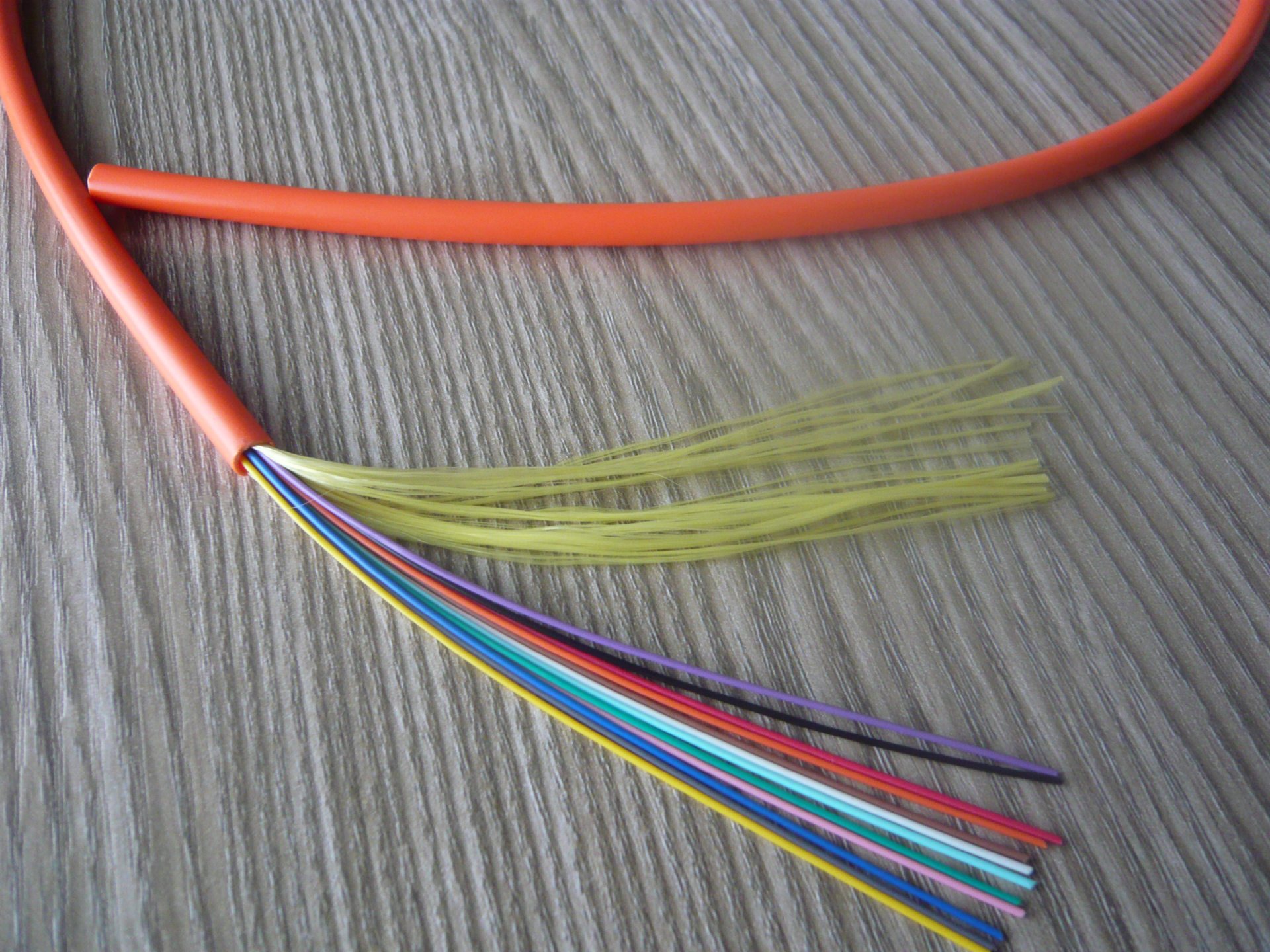
The fiber optic cable consists of a core, cladding, and protective coating. The core, typically made of glass or plastic, is where the light travels. The cladding, with a lower refractive index, keeps the light within the core through total internal reflection. The protective coating shields the fiber from physical damage and environmental factors.
Fiber optic connectors are critical components that enable the connection between fiber optic cables and network devices. These precision-engineered devices align the fiber cores to ensure efficient light transmission with minimal loss. The performance of a fiber optic system heavily depends on the quality of both the fiber optic cable and connectors.
Key Advantages of Fiber Optic Cable and Connectors
- High bandwidth capacity (up to terabits per second)
- Low signal attenuation (0.2-0.5 dB/km)
- Immunity to electromagnetic interference
- Lightweight and thinner than copper cables
- Enhanced security and reduced signal leakage
- Longer transmission distances (up to 100 km without amplification)
Applications of Fiber Optic Cable and Connectors
- Telecommunication networks (long-distance and metropolitan)
- Data centers and high-performance computing
- Fiber-to-the-Home (FTTH) and broadband access networks
- Cable television (CATV) systems
- Industrial automation and control systems
- Military and aerospace applications
Fiber Optic Cable Types and Specifications
Single-Mode Fiber (SMF)
Single-mode fiber optic cable has a small core diameter (typically 8-10 μm) that allows only one mode of light to propagate. This results in minimal modal dispersion, enabling high-bandwidth transmission over long distances.
Key Specifications:
- Core/Cladding Diameter: 9/125 μm
- Attenuation (1310 nm): ≤ 0.35 dB/km
- Attenuation (1550 nm): ≤ 0.22 dB/km
- Bandwidth: Virtually unlimited
- Maximum Distance: Up to 100 km
Commonly used in long-haul telecommunications, submarine cables, and high-speed data center interconnects.
Multi-Mode Fiber (MMF)
Multi-mode fiber optic cable has a larger core diameter (50-62.5 μm) that allows multiple modes of light to propagate simultaneously. This results in modal dispersion, limiting transmission distance but offering higher light-gathering capacity.
Key Specifications:
- Core/Cladding Diameter: 50/125 μm or 62.5/125 μm
- Attenuation (850 nm): ≤ 3.5 dB/km
- Attenuation (1300 nm): ≤ 1.0 dB/km
- Bandwidth (OM4 at 850 nm): 4700 MHz·km
- Maximum Distance: Up to 550 m (OM4 at 10 Gbps)
Commonly used in short-distance applications such as local area networks (LANs), data centers, and premises cabling.
Fiber Optic Cable Construction Types
| Construction Type | Description | Applications | Advantages |
|---|---|---|---|
| Loose Tube | Fibers are placed in buffered tubes filled with water-blocking gel | Outdoor, aerial, underground, submarine | High tensile strength, water-resistant, rodent-proof |
| Tight Buffer | Fibers are coated with a tight buffer layer (900 μm) | Indoor, premise cabling, patch cords | Flexible, easy to terminate, cost-effective |
| Ribbon | Fibers are arranged in parallel in a flat ribbon structure | High-density applications, data centers | High fiber count, space-saving, fast termination |
| Armored | Additional metal or非金属 armor layer for protection | Harsh environments, industrial, military | Enhanced mechanical protection, crush resistance |
Fiber Optic Cable Performance Characteristics
Attenuation
Attenuation is the loss of signal strength as light travels through the fiber optic cable. It is measured in decibels per kilometer (dB/km) and varies with wavelength.
Typical Attenuation Values:
- Single-mode at 1310 nm: 0.35 dB/km
- Single-mode at 1550 nm: 0.22 dB/km
- Multi-mode at 850 nm: 3.5 dB/km
- Multi-mode at 1300 nm: 1.0 dB/km
Dispersion
Dispersion causes the light pulses to spread as they travel through the fiber, limiting the bandwidth and transmission distance.
Types of Dispersion:
- Modal Dispersion: Occurs in multi-mode fibers due to different path lengths of light modes
- Chromatic Dispersion: Occurs because different wavelengths travel at different speeds
- Polarization Mode Dispersion (PMD): Occurs in single-mode fibers due to birefringence
Bandwidth
Bandwidth is the information-carrying capacity of a fiber optic cable, typically measured in MHz·km for multi-mode fibers. Single-mode fibers have virtually unlimited bandwidth.
Multi-Mode Fiber Bandwidth Ratings:
- OM1 (62.5/125): 200 MHz·km at 850 nm
- OM2 (50/125): 500 MHz·km at 850 nm
- OM3 (50/125): 2000 MHz·km at 850 nm
- OM4 (50/125): 4700 MHz·km at 850 nm
- OM5 (50/125): 4700 MHz·km at 850 nm and 950 nm
Fiber Optic Connector Types and Performance
LC Connector
Small form factor connector with 1.25mm ferrule, ideal for high-density applications.
SC Connector
Square connector with 2.5mm ferrule, commonly used in telecom and data communications.
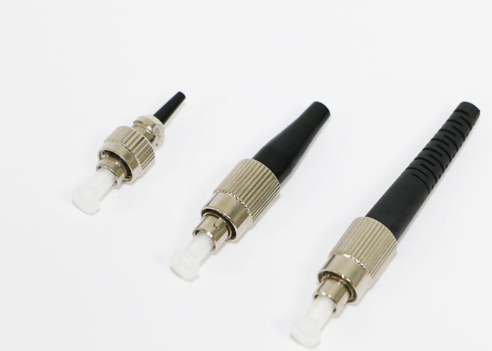
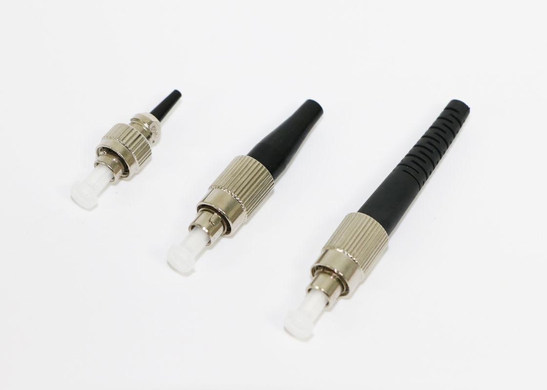
FC Connector
Threaded connector with 2.5mm ferrule, offering excellent stability in high-vibration environments.
Fiber Optic Connector Performance Comparison
| Connector Type | Ferrule Size | Insertion Loss (UPC) | Return Loss (UPC) | Return Loss (APC) | Mating Cycles | Applications |
|---|---|---|---|---|---|---|
| LC | 1.25 mm | ≤ 0.2 dB | ≥ 55 dB | ≥ 65 dB | 500 | Data centers, high-density |
| SC | 2.5 mm | ≤ 0.3 dB | ≥ 50 dB | ≥ 60 dB | 1000 | FTTH, LAN, CATV |
| FC | 2.5 mm | ≤ 0.25 dB | ≥ 50 dB | ≥ 60 dB | 500 | High-vibration, test equipment |
| ST | 2.5 mm | ≤ 0.3 dB | ≥ 40 dB | N/A | 500 | Legacy networks, industrial |
| MPO/MTP | 2.5 mm (12/24 fibers) | ≤ 0.35 dB | ≥ 45 dB | ≥ 55 dB | 500 | High-speed networks, 40/100G |
Connector Endface Polishing Types
PC (Physical Contact)
Flat endface with a slight curvature to ensure physical contact between fibers.
UPC (Ultra Physical Contact)
Enhanced PC polish with a more rounded endface for better contact and lower reflection.
APC (Angled Physical Contact)
8° angled endface that redirects reflected light into the cladding, minimizing back reflection.
Connector Endface Inspection
Proper inspection and cleaning of fiber optic connector endfaces are critical for maintaining optimal performance. Contaminants such as dust, oil, and debris can significantly increase insertion loss and reduce return loss.
Endface Inspection Requirements (per IEC 61300-3-35):
- No scratches deeper than 0.5 μm
- No particles larger than 5 μm in the core area
- No more than 10 particles between 1-5 μm in the core area
- No staining or discoloration
Technical Specifications and Performance Data
Fiber Optic Cable Attenuation Characteristics
Attenuation is caused by several factors, including absorption, scattering, and bending. The chart above shows typical attenuation values for different fiber types across various wavelengths.
Fiber Optic Connector Performance Under Environmental Stress
| Environmental Factor | Test Condition | Performance Requirement | Typical Performance |
|---|---|---|---|
| Temperature | -40°C to +85°C (1000 cycles) | ΔIL ≤ 0.3 dB | ΔIL ≤ 0.15 dB |
| Humidity | 85% RH, 85°C (1000 hours) | ΔIL ≤ 0.3 dB | ΔIL ≤ 0.2 dB |
| Vibration | 10-2000 Hz, 20 G | ΔIL ≤ 0.3 dB | ΔIL ≤ 0.1 dB |
| Shock | 100 G, 1 ms | ΔIL ≤ 0.3 dB | ΔIL ≤ 0.1 dB |
| Salt Fog | 5% NaCl, 40°C (1000 hours) | No corrosion, ΔIL ≤ 0.3 dB | No corrosion, ΔIL ≤ 0.15 dB |
Authoritative Literature Reference
"Fiber optic connectors play a critical role in ensuring reliable and efficient data transmission in fiber optic networks. When choosing a fiber connector, it's essential to consider factors such as insertion loss, return loss, and compatibility with the network equipment. Three common types of fiber connectors are PC (Physical Contact), UPC (Ultra Physical Contact), and APC (Angled Physical Contact)."
"APC connectors have an angled end face with an 8-degree angle. The angled design minimizes back reflection by redirecting reflected light away from the source. APC connectors provide the highest return loss performance among the three connector types."
Source: ZR Cable Group. (2025). "PC vs UPC vs APC Connector: Selecting the Right Fiber Connector Type." Retrieved from https://www.zrcable.com/knowledge/PC-vs-UPC-vs-APC-Connector--Selecting-the-Right-Fiber-Connector-Type.html
Latest Research on Fiber Optic Cable and Connectors
Development of Re-assemblable Multifiber Connector for Co-Packaged Optics
This research presents a molded product multifiber connector that can be reassembled before and after the reflow process. Evaluation results show that the connector can provide similar performance as a standard MPO connector with a smaller footprint.
Source: Setiawan Putra, A. W., Matsuda, K., & Takezaki, M. (2024). Development of Re-assemblable Multifiber Connector for Co-Packaged Optics. In 2024 IEEE CPMT Symposium Japan (ICSJ). IEEE.
Slim Push-Pull Fiber Array Connector for Optical Chips
This study reports a connector loss of 0.42 dB for a low-profile fiber-to-chip connector designed to replace fiber pigtails and enable flip-chip electronic assembly of optical chips for co-packaged optics.
Source: Brusberg, L., Matthies, J., Grenier, J. R., Clark, J. S., Johnson, B. J., & Terwilliger, C. C. (2023). Slim Push-Pull Fiber Array Connector for Optical Chips. In 2023 Optical Fiber Communications Conference and Exhibition (OFC). IEEE.
Applications of Fiber Optic Cable and Connectors
Data Centers
Fiber optic cable and connectors are widely used in data centers to support high-speed data transmission between servers, storage systems, and network switches. The high bandwidth and low latency of fiber optic technology make it ideal for meeting the increasing demands of cloud computing, big data, and artificial intelligence applications.
Common Data Center Applications:
- High-density interconnects (HDIs)
- Top-of-rack (ToR) to end-of-row (EoR) connections
- Data center interconnects (DCIs)
- Storage area networks (SANs)
- High-performance computing (HPC) clusters
Fiber-to-the-Home (FTTH)
FTTH networks use fiber optic cable and connectors to deliver high-speed broadband services directly to homes and businesses. This technology provides significantly higher bandwidth than traditional copper-based systems, enabling services such as high-definition video streaming, online gaming, and video conferencing.
FTTH Deployment Considerations:
- Passive Optical Networks (PONs) architecture
- GPON/EPON technologies
- Drop cable design and installation
- Optical Network Terminals (ONTs)
- Connector reliability in outdoor environments
Telecommunication Networks
Fiber optic cable and connectors form the backbone of modern telecommunication networks, enabling long-distance voice, data, and video transmission. These networks require high reliability, low latency, and large bandwidth capacity to support the growing demands of global communication.
Telecommunication Network Applications:
- Long-haul backbone networks
- Metropolitan area networks (MANs)
- Submarine communication cables
- Mobile backhaul for 4G/5G networks
- Core network interconnects
Industrial and Harsh Environment Applications
Fiber optic cable and connectors are increasingly used in industrial environments due to their immunity to electromagnetic interference, resistance to corrosion, and ability to operate in extreme temperatures. These characteristics make them ideal for applications in manufacturing, energy, transportation, and military systems.
Industrial Application Requirements:
- Armored and ruggedized cable designs
- High-temperature and chemical resistance
- IP68-rated connectors for dust and water protection
- Shock and vibration resistance
- Long-term reliability in harsh conditions
Frequently Asked Questions (FAQs)
What is the difference between single-mode and multi-mode fiber optic cable?
Single-mode fiber has a small core diameter (typically 8-10 μm) that allows only one mode of light to propagate, resulting in minimal dispersion and enabling high-bandwidth transmission over long distances (up to 100 km). Multi-mode fiber has a larger core diameter (50-62.5 μm) that allows multiple modes of light to propagate, which limits transmission distance but offers higher light-gathering capacity for short-distance applications (up to 550 m for OM4 fiber at 10 Gbps).
What are the key performance parameters for fiber optic connectors?
The key performance parameters for fiber optic connectors include insertion loss (the amount of light lost at the connection), return loss (the amount of light reflected back toward the source), repeatability (consistency of performance after multiple mating cycles), and durability (number of mating cycles the connector can withstand). Other important factors include environmental performance (temperature, humidity, vibration resistance) and mechanical characteristics (alignment, coupling mechanism).
How do I choose the right fiber optic connector for my application?
When choosing a fiber optic connector, consider factors such as: 1) Application requirements (data center, FTTH, industrial, etc.), 2) Performance needs (insertion loss, return loss), 3) Density requirements (LC for high density, SC for standard density), 4) Environmental conditions (temperature, humidity, vibration), 5) Cost considerations, and 6) Compatibility with existing equipment. For example, LC connectors are ideal for high-density data center applications, while SC connectors are commonly used in FTTH deployments, and FC connectors are preferred for high-vibration environments.
How do I properly clean and maintain fiber optic connectors?
Proper cleaning and maintenance of fiber optic connectors are critical for optimal performance. Follow these steps: 1) Inspect the connector endface using a fiber optic microscope, 2) Use a lint-free cleaning wipe with isopropyl alcohol (91% or higher) to clean the endface in a circular motion, 3) For bulkhead connectors, use a connector cleaning tool with a dry cleaning tape or swab, 4) Re-inspect after cleaning to ensure no contaminants remain, 5) Always cover connectors with dust caps when not in use, and 6) Establish a regular cleaning schedule based on application and environmental conditions. Avoid touching the endface with bare fingers, as oils and debris can cause signal degradation.
What are the common causes of fiber optic connector failure?
Common causes of fiber optic connector failure include: 1) Contamination of the endface (dust, oil, debris), 2) Physical damage to the ferrule or endface (scratches, chips), 3) Improper installation or mating (excessive force, misalignment), 4) Environmental factors (temperature extremes, humidity, corrosion), 5) Wear and tear from repeated mating cycles, and 6) Manufacturing defects. Regular inspection, proper cleaning, and careful handling can significantly reduce the risk of connector failure and ensure reliable performance of fiber optic systems.
What are the future trends in fiber optic cable and connector technology?
Future trends in fiber optic cable and connector technology include: 1) Higher density connectors to support increasing data center demands, 2) Smaller form factor designs for space-constrained applications, 3) Improved performance (lower insertion loss, higher return loss), 4) Enhanced environmental resistance for harsh conditions, 5) Integration with photonic integrated circuits (PICs) for co-packaged optics, 6) Development of multi-fiber connectors for parallel optics and high-speed networks (400G, 800G, and beyond), and 7) Advances in fiber optic cable design for higher bandwidth and longer transmission distances. These innovations will continue to support the growing demands for high-speed, reliable, and efficient data transmission in various applications.
Glossary of Fiber Optic Terms
A-C
- Attenuation
- The loss of signal strength as light travels through the fiber optic cable, measured in decibels per kilometer (dB/km).
- APC (Angled Physical Contact)
- A fiber optic connector polishing method with an 8° angled endface that redirects reflected light into the cladding, minimizing back reflection.
- Bandwidth
- The information-carrying capacity of a fiber optic cable, typically measured in MHz·km for multi-mode fibers.
- Cladding
- The layer surrounding the fiber core that has a lower refractive index, keeping light within the core through total internal reflection.
- Core
- The central part of a fiber optic cable where light travels, typically made of glass or plastic.
D-H
- Dispersion
- The spreading of light pulses as they travel through the fiber, which can limit bandwidth and transmission distance.
- Ferrule
- A precision-made component that holds the fiber in place and aligns fibers in a connector.
- Insertion Loss
- The amount of optical power lost at a connection point, typically expressed in decibels (dB).
- LC Connector
- A small form factor fiber optic connector with a 1.25mm ferrule, commonly used in high-density applications.
- Multi-Mode Fiber (MMF)
- A type of fiber optic cable with a larger core diameter that allows multiple modes of light to propagate.
I-M
- PC (Physical Contact)
- A fiber optic connector polishing method with a flat endface that comes into direct physical contact with the mating connector.
- PMD (Polarization Mode Dispersion)
- A type of dispersion in single-mode fibers caused by birefringence, which can limit bandwidth at high speeds.
- Return Loss
- The amount of light reflected back toward the source at a connection point, expressed in decibels (dB).
- SC Connector
- A square fiber optic connector with a 2.5mm ferrule, commonly used in telecom and data communications.
- Single-Mode Fiber (SMF)
- A type of fiber optic cable with a small core diameter that allows only one mode of light to propagate.
N-Z
- UPC (Ultra Physical Contact)
- An enhanced PC polishing method with a slight spherical endface that provides better physical contact and lower reflection.
- VAD (Vapor Axial Deposition)
- A method for manufacturing optical fibers by depositing silica soot on a rotating mandrel in a furnace.
- Wavelength
- The distance between two consecutive peaks of a light wave, typically measured in nanometers (nm) for fiber optics.
- ZBLAN
- A family of fluoride glasses with very low attenuation in the mid-infrared region, used for specialty fiber optic applications.
Learn More About Fiber Optic Cable and Connectors
Explore our comprehensive resources to deepen your understanding of fiber optic technology and its applications in modern communication systems.
Learn more