DWDM Key Technologies
The Most Mature and Perfect Industry Solution for Cable and Fiber Optic Communication Networks

Dense Wavelength Division Multiplexing
DWDM technology revolutionizes cable and fiber optic communications by enabling multiple wavelengths of light to be transmitted simultaneously over a single optical fiber, dramatically increasing bandwidth capacity and transmission efficiency.
Light Source Technology
Advanced laser diodes and wavelength conversion technologies form the foundation of high-performance DWDM systems.
Multiplexers & Switches
Precision components that combine and route multiple wavelengths with minimal loss and interference.
Optical Amplification
Erbium-doped fiber amplifiers (EDFAs) and Raman amplifiers extend transmission distances without signal degradation.
Fiber Optic Cables
Specialized fibers optimized for minimal loss, dispersion, and nonlinear effects in DWDM systems.
1. Light Source and Wave Conversion Technology
The quality of light sources is critical to the performance of DWDM systems. Single-frequency lasers with narrow linewidth and high stability are essential for minimizing crosstalk and maximizing channel density.
Key Light Source Requirements
- Ultra-narrow linewidth (<100 kHz)
- High wavelength stability (<±10 pm over temperature variations)
- Low relative intensity noise (RIN <-155 dB/Hz)
- High output power (typically 0 to 5 dBm)
- Low chirp for high-speed modulation
Types of Laser Sources for DWDM
Distributed Feedback (DFB) Lasers
Most common laser type for DWDM, providing single-mode operation with narrow linewidth and high stability.
Vertical Cavity Lasers (VCLs)
Tunable lasers that can be adjusted to different wavelengths, enabling flexible wavelength assignment.
External Grating Lasers (DBRs)
Provide excellent wavelength stability and narrow linewidth, suitable for high-density DWDM systems.
Wavelength Conversion Technology
Wavelength converters, also known as Optical Transponders (OTUs), play a crucial role in modern DWDM systems by converting non-standard wavelengths from client equipment to standardized DWDM wavelengths. This enables interoperability between different vendors' equipment and allows for flexible network design.
O/E/O Conversion
The most common type of wavelength conversion, Optical-to-Electrical-to-Optical conversion involves:
- Converting the incoming signal to an electrical signal
- Regenerating and reshaping the electrical signal
- Re-modulating a new laser at the desired wavelength
This method provides signal regeneration, improving signal quality but introducing some latency.
All-Optical Conversion
Emerging technology that converts wavelengths without electrical intermediation using:
- Semiconductor Optical Amplifiers (SOAs)
- Four Parametric Amplifiers (OPAs)
- Non Nonlinearities in specialty fibers
All-optical conversion offers lower latency and higher transparency to data formats but is currently more complex and expensive.
Modulation Techniques for DWDM
Advanced modulation format significantly impacts the performance of DWDM systems, affecting spectral efficiency, reach, and tolerance to impairments. Advanced modulation formats enable higher data rates and greater spectral efficiency in cable and fiber optic networks.
| Modulation Format | Data Rate per Wavelength | Spectral Efficiency | Reach | Applications |
|---|---|---|---|---|
| NRZ (Non-Return-to-Zero) | Up to 10 Gbps | 0.4 bits/s/Hz | Long | Metro and long-haul |
| RZ (Return-to-Zero) | Up to 40 Gbps | 0.8 bits/s/Hz | Medium | Long-haul |
| DQPSK | 40 Gbps | 1.6 bits/s/Hz | Long | Long-haul, submarine |
| 16-QAM | 100 Gbps | 3.2 bits/s/Hz | Medium | Metro, regional |
| 64-QAM | 200-400 Gbps | 4.8 bits/s/Hz | Short | Data center interconnects |
2. Optical Multiplexers/Demultiplexers and Optical Switches
These components are the backbone of DWDM systems, enabling the combination, separation, and routing of multiple wavelengths of light in cable and fiber optic networks.
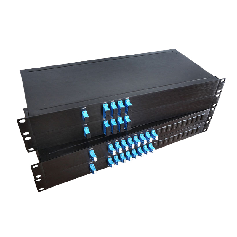
Optical Multiplexers (MUX)
Multiplexers combine multiple optical signals of different wavelengths onto a single optical fiber. The performance of MUX components directly impacts the overall system capacity and signal quality.
Key Performance Parameters
- Low insertion loss (typically <3 dB)
- High channel isolation (>25 dB)
- Flat passband for minimal signal distortion
- Low polarization-dependent loss (PDL)
- High temperature stability
Common MUX Technologies
Arrayed Waveguide Gratings (AWGs)
Planar lightwave circuit devices that use diffraction to separate or combine wavelengths. Ideal for high-channel-count systems.
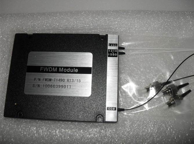
Dielectric Thin-Film Filters
Layered filters that transmit specific wavelengths while reflecting others. Excellent for low-channel-count systems and add-drop applications.
Fiber Bragg Gratings (FBGs)
Periodic variations in fiber refractive index that reflect specific wavelengths. Used in add-drop multiplexers and dispersion compensation.
Optical Demultiplexers (DEMUX)
Demultiplexers separate the combined optical signals from a single fiber back into individual wavelengths for detection by separate receivers.
DWDM Multiplexer/Demultiplexer Unit
Add-Drop Multiplexers (ADMs)
ADMs allow specific wavelengths to be added to or dropped from a DWDM signal without affecting other channels. This enables flexible network topologies and wavelength routing.
ADM Applications
- Regional and metro networks
- Data center interconnects
- 5G backhaul networks
- CATV distribution networks
Optical Switches
Optical switches enable dynamic routing of optical signals in a network, providing flexibility, redundancy, and efficient resource utilization. They are essential components in reconfigurable optical add-drop multiplexers (ROADMs) and optical cross-connects (OXCs).
Types of Optical Switches
Mechanical Switches
Physically move fiber or free-space optical components. Offer low insertion loss and high isolation but relatively slow switching speeds (ms range).
Micro-Electro-Mechanical Systems (MEMS)
Miniaturized mechanical switches on a chip. Offer high port counts and moderate switching speeds (μs range).
Liquid Crystal Switches
Use liquid crystal cells to control light polarization and direction. Offer fast switching speeds (ns range) but higher insertion loss.
Semiconductor Optical Amplifier (SOA) Switches
Use SOAs as both amplifiers and switches. Offer gain, fast switching, and integration potential but have higher crosstalk.
Optical Switch Animation
Switch Performance Metrics
| Switch Type | Insertion Loss | Isolation | Switching Speed | Port Count |
|---|---|---|---|---|
| Mechanical | <1 dB | >60 dB | 1-100 ms | Up to 256 |
| MEMS | 1-2 dB | 40-50 dB | 10-100 μs | Up to 1024 |
| Liquid Crystal | 2-3 dB | 30-40 dB | 10-100 ns | Up to 64 |
| SOA | 0-1 dB (gain) | 20-30 dB | <1 ns | Up to 16 |
Reconfigurable Optical Add-Drop Multiplexers (ROADMs)
ROADMs are advanced optical components that combine the functions of multiplexers, demultiplexers, and optical switches. They enable remote configuration and dynamic adjustment of wavelength routing without manual intervention, making them essential for flexible, scalable cable and fiber optic networks.
Colorless ROADMs
Allow any wavelength to be added or dropped on any port, providing flexibility in wavelength assignment.
Directionless ROADMs
Enable wavelength routing in any direction, simplifying network design and increasing flexibility.
Contentionless ROADMs
Prevent wavelength conflicts when adding/dropping, allowing multiple connections to use the same wavelength in different directions.
ROADM Network Benefits
- Rapid service provisioning and reconfiguration
- Reduced operational costs through automation
- Improved network resilience and fault recovery
- Support for dynamic bandwidth allocation
- Enablement of software-defined optical networks (SDON)
3. Optical Amplification Technology
Optical amplifiers are critical components in DWDM systems, enabling long-distance transmission by boosting signal strength without converting between optical and electrical domains.
Erbium-Doped Fiber Amplifiers (EDFAs)
EDFAs are the workhorse of DWDM systems, providing high gain, low noise, and wide bandwidth in the C-band (1530-1565 nm) and L-band (1565-1625 nm) regions.
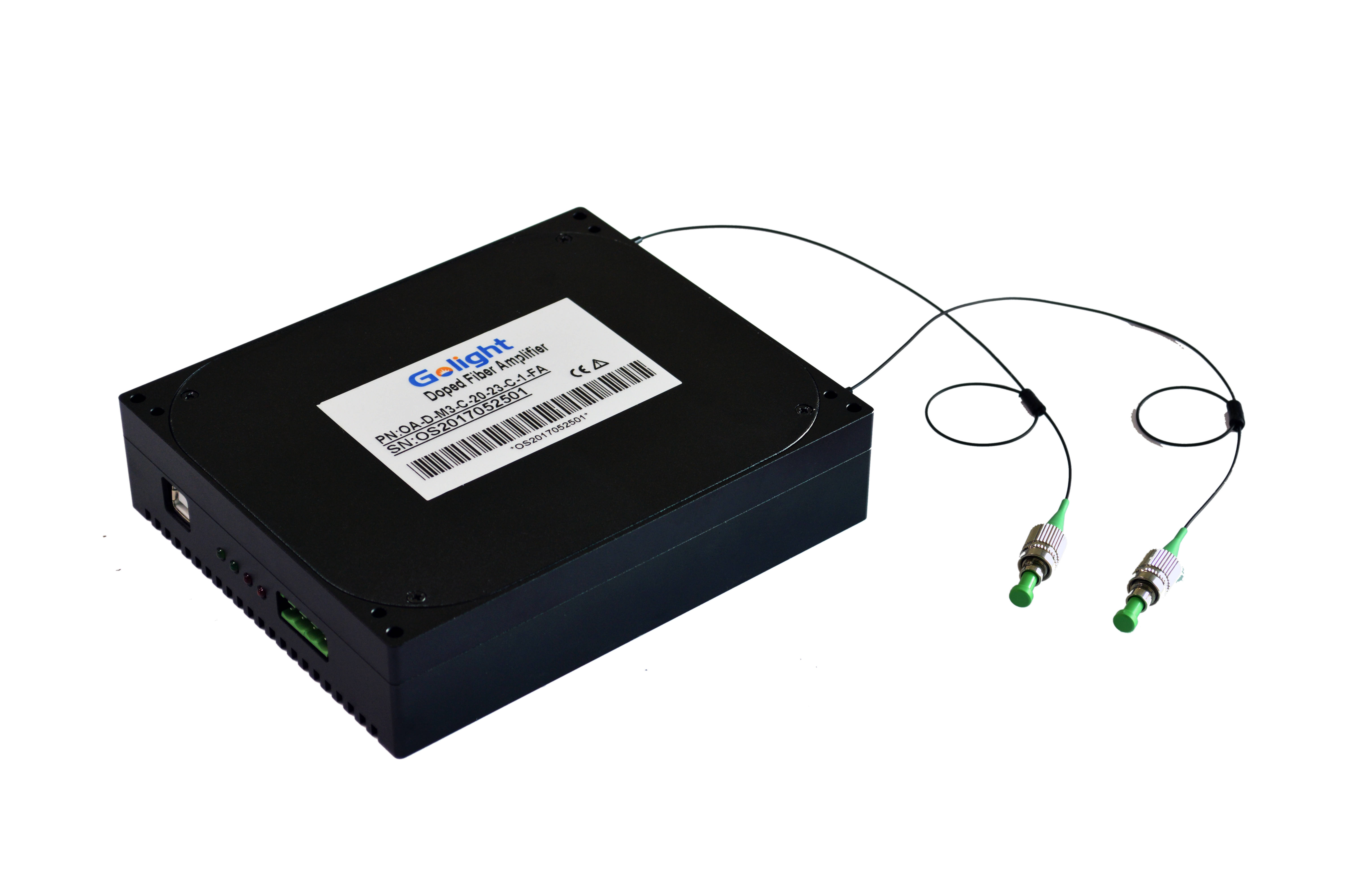
Erbium-Doped Fiber Amplifier (EDFA) Module
EDFA Working Principle
- Pump lasers (typically 980 nm or 1480 nm) excite erbium ions in the fiber
- Excited erbium ions release energy as photons when stimulated by signal light
- This stimulated emission amplifies the input signal
- Isolators prevent feedback and ensure unidirectional operation
EDFA Advantages
- Broad bandwidth (up to 80 nm)
- Low noise figure (3-5 dB)
- High gain (20-40 dB)
- Bit-rate and modulation-format transparent
- Ability to amplify multiple wavelengths simultaneously
Raman Amplifiers
Raman amplifiers utilize stimulated Raman scattering (SRS) in optical fibers to provide distributed amplification, offering unique advantages for long-haul and submarine cable and fiber optic systems.
Types of Raman Amplifiers
Distributed Raman Amplifiers
Pump light is injected counter-propagating to the signal, providing amplification along the transmission fiber itself. This reduces noise accumulation and improves signal quality.
Discrete Raman Amplifiers
Use a short length of high-nonlinearity fiber for amplification. Offer higher gain per unit length but with higher noise figures than distributed amplifiers.
Raman Amplifier Advantages
- Broad amplification bandwidth (1270-1670 nm)
- Low noise figure when used as pre-amplifiers
- Distributed amplification reduces nonlinear effects
- Can be used to extend EDFA bandwidth
- Suitable for ultra-long-haul and submarine applications
Amplifier Configurations in DWDM Systems
Different amplifier configurations are used in DWDM systems depending on their position and function in the network. These configurations optimize performance for specific applications and transmission distances.
Booster Amplifiers (BA)
Located after the multiplexer, booster amplifiers increase signal power before transmission over long distances. They typically provide 20-30 dB gain and output powers of 10-20 dBm.
In-Line Amplifiers (LA)
Placed periodically along the transmission path to compensate for fiber loss. In-line amplifiers typically provide 15-25 dB gain and are spaced 80-120 km apart in terrestrial systems.
Pre-Amplifiers (PA)
Located before the demultiplexer, pre-amplifiers boost weak incoming signals to a level suitable for detection. They prioritize low noise figure (3-4 dB) over maximum gain.
Amplifier Performance Comparison
| Amplifier Type | Operating Band | Gain | Noise Figure | Output Power | Applications |
|---|---|---|---|---|---|
| C-band EDFA | 1530-1565 nm | 20-40 dB | 3-5 dB | 10-23 dBm | Terrestrial, metro, long-haul |
| L-band EDFA | 1565-1625 nm | 15-35 dB | 4-6 dB | 8-20 dBm | Long-haul, ultra-long-haul |
| Distributed Raman | 1270-1670 nm | 10-20 dB | 2-4 dB | Depends on span | Ultra-long-haul, submarine |
| Hybrid EDFA-Raman | 1530-1625 nm | 25-45 dB | 3-5 dB | 15-25 dBm | Ultra-long-haul, submarine |
Amplifier Challenges and Solutions
While optical amplifiers enable long-distance transmission, they also introduce challenges that must be addressed to maintain signal quality in DWDM systems.
Gain Flatness
EDFAs exhibit wavelength-dependent gain, which can lead to uneven signal levels across the DWDM spectrum. This problem is exacerbated in multi-span systems.
Solutions:
- Gain Flattening Filters (GFFs)
- Optimized erbium doping profiles
- Multi-stage amplifier designs
- Dynamic gain equalization
Amplifier Noise
Amplifier noise, primarily Amplified Spontaneous Emission (ASE), degrades signal-to-noise ratio (SNR) and limits transmission distance.
Solutions:
- Low-noise pre-amplifiers
- Distributed Raman amplification
- Optimized amplifier cascading
- Noise loading techniques
Stimulated Raman Scattering (SRS)
SRS causes power transfer from short-wavelength channels to longer-wavelength channels, creating inter-channel crosstalk and signal distortion.
Solutions:
- Channel power equalization
- Non-uniform channel spacing
- Reduced launch power per channel
- Forward error correction (FEC)
Amplifier Transients
Adding or dropping channels can cause transient power fluctuations in EDFAs, potentially leading to signal degradation or equipment damage.
Solutions:
- Automatic gain control (AGC)
- Power excursion control
- Slow channel addition/dropping
- Transient suppression algorithms
Advanced Amplification Techniques
Multi-Core Fiber Amplifiers
Amplifiers designed for multi-core fibers, enabling spatial division multiplexing (SDM) and further increasing transmission capacity.
Coherent Amplification
Combines coherent detection with advanced digital signal processing (DSP) to mitigate amplifier impairments and improve system performance.
Integrated Photonic Amplifiers
Miniaturized amplifiers on photonic integrated circuits (PICs), offering reduced size, power consumption, and cost.
4. Fiber Optic Cable Technology
The performance of DWDM systems is heavily dependent on the characteristics of the optical fiber used. Specialized fiber designs optimize for low loss, minimal dispersion, and reduced nonlinear effects.
Fiber Optic Cable Structure
Modern optical fibers consist of several layers, each designed to optimize signal transmission and protect the delicate glass core.
Fiber Optic Cable Components
Core
The central glass region where light is transmitted. Typically 8-10 μm in diameter for single-mode fiber.
Cladding
A glass layer surrounding the core with a lower refractive index, causing light to reflect back into the core (total internal reflection).
Coating
A protective polymer layer (typically 250 μm) that protects the glass from physical damage and environmental factors.
Jacket
An outer protective layer (typically 900 μm) that provides mechanical protection and identifies fiber type.
Fiber Types for DWDM
Different fiber types are optimized for specific applications and performance characteristics, making them suitable for different DWdm system requirements.
Indoor Multi-mode Fiber Optic Cable
Common Fiber Types
G.652 - Standard Single-Mode Fiber (SMF)
The most widely deployed fiber type, optimized for 1310 nm but also used in the C-band (1530-1565 nm) with dispersion compensation. Zero dispersion at 1310 nm.
G.653 - Dispersion-Shifted Fiber (DSF)
Zero dispersion shifted to the C-band (1550 nm), making it suitable for high-speed, long-distance transmission. However, it suffers from four-wave mixing (FWM) in DWDM systems.
G.655 - Non-Zero Dispersion-Shifted Fiber (NZ-DSF)
Optimized for DWDM systems with non-zero dispersion in the C-band, reducing nonlinear effects while maintaining low dispersion. Available in two variants: C-band optimized (G.655.A/B) and wideband (G.655.C/D).
G.657 - Bend-Insensitive Fiber
Designed for improved bending performance, making it suitable for FTTH (Fiber-to-the-Home) and data center applications where tight bends are common.
Fiber Transmission Characteristics
The performance of DWDM systems is significantly influenced by key fiber characteristics, including attenuation, dispersion, and nonlinear effects.
Attenuation
Signal loss as light travels through the fiber, primarily caused by absorption and scattering. Measured in dB/km. Modern fibers have minimum attenuation around 0.18 dB/km in the C-band.
Dispersion
Pulse spreading caused by different wavelengths traveling at different speeds. Chromatic dispersion is measured in ps/(nm·km) and limits transmission distance and data rate.
Nonlinear Non Effects
Nonlinear interactions between light waves in the fiber, including self-phase-phase modulation (SPM), cross-phase modulation (XPM), and four-wave mixing (FWM).
Advanced Fiber Technologies
Emerging fiber technologies are pushing the boundaries of DWDM system performance, enabling higher capacities, longer distances, and more efficient use of the optical spectrum.
Large Effective Area Fibers
Fibers with larger core diameters (effective area > 100 μm²) reduce optical power density, mitigating nonlinear effects and allowing higher launch powers. Examples include Corning LEAF® and Alcatel-Lucent TeraLight® fibers.
Benefits:
- Reduced nonlinear effects
- Higher launch powers possible
- Extended transmission distances
- Improved performance in high-channel-count DWdm systems
Photonic Band Dispersion-Shifted Fibers
Fibers with modified refractive index profiles that shift the zero-dispersion wavelength outside the C-band, reducing four-wave mixing while maintaining low dispersion in the operating band.
Types:
- Non-zero dispersionation-shifted fiber (NZ-DSF)
- TrueWave® RS and XL fibers
- LEAF® and Vascade® fibers
Multi-Core Fibers (MCFs)
Fibers containing multiple multiple parallel cores, each acting as an independent transmission channel. This spatial division multiplexing (SDM) technique dramatically increases overall capacity.
Types:
- Uncoupled MCF (independent cores)
- Weakly coupled MCF (some crosstalk between cores)
- Strongly coupled MCF (mode-division multiplexing)
Hollow-Core Fibers
Fibers with a hollow central core surrounded by a photonic crystal structure that guides light through the air-filled core. This dramatically reduces nonlinear effects and signal loss.
Potential Benefits:
- Near-zero nonlinear effects
- Lower attenuation than solid-core fibers
- Immunity to radiation-induced effects
- Potential for ultra-high-speed, ultra-long-haul transmission
Fiber Cable Deployment Considerations
Indoor Cabling
Requires flexibility, flame resistance, and often higher fiber counts. Common types include distribution, breakout, and ribbon cables.
Outdoor Cabling
Requires protection against moisture, temperature extremes, and physical damage. Common types include loose-tube, armored, and aerial cables.
Submarine Cabling
Requires extreme protection against water pressure, corrosion, and marine life. Thick armor layers and special coatings are used for deep-sea applications.
DWDM Technology Evolution
The evolution of DWDM technology has been marked by continuous improvements in capacity, reach, and efficiency, driven by advances in cable and fiber optic technologies.
1990s - Early DWDM
First commercial DWDM systems with 4-16 channels, 200 GHz spacing, and 2.5 Gbps per channel. Introduction of EDFA technology revolutionizes long-haul transmission.
2000s - Mid-Range DWDM
32-40 channel systems with 100 GHz spacing become standard. 10 Gbps per channel becomes common. Introduction of dispersion compensation technologies and Raman amplification.
2010s - High-Density DWDM
80-160 channel systems with 50 GHz spacing. 40 Gbps and 100 Gbps per channel using advanced modulation formats (DQPSK, 16-QAM). ROADMs enable flexible network architectures.
2020s - Ultra-High Capacity
400 Gbps and 800 Gbps per channel become commercial. Introduction of 64-QAM and higher-order modulation. C+L band systems double capacity. AI/ML optimization for network management.
Future - Beyond 1 Tbps
1.6 Tbps and higher per channel. Spatial division multiplexing (SDM) with multi-core fibers. Quantum communication integration. Autonomous self-optimizing networks.
Interactive DWDM Technology Demo
Explore how different DWDM components work together to enable high-capacity optical transmission in modern cable and fiber optic networks.
Transmitter
MUX
Amplifier
Receiver
Transmitter Status
Idle
MUX Status
Idle
Amplifier Status
Idle
Receiver Status
Idle
The Future of DWDM Technology
As data traffic continues to grow exponentially, DWDM technology will remain at the forefront of cable and fiber optic communication networks, enabling the high-capacity, long-distance transmission required for the digital age.
Increasing Capacity
Continued advancements in modulation formats, spectral efficiency, and spatial division multiplexing will push DWDM capacities well beyond 100 Tbps per fiber pair.
Network Intelligence
AI and machine learning will play an increasingly important role in optimizing DWDM network performance, enabling self-healing, predictive maintenance, and dynamic resource allocation.
Integration and Miniaturization
Photonic integrated circuits (PICs) will continue to reduce the size, cost, and power consumption of DWDM components, enabling more compact and efficient network equipment.